Full code checking can be performed on Dimension Lumber and Post and Timber size wood shapes based on the following codes:
Note
Information on the design of "Wood Products", such as wood I-joists, may be found in the Wood Products topic.
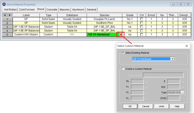
Glu-Lams are treated as any other wood species and may be selected from the list of species on the Wood tab of the Materials spreadsheet.
Available Glulam Materials are per Tables 5A and 5C of the NDS Supplement and Table 6.3 of the CSA O86. When a Glu-Lam is selected, the grade will be listed as "na" or not applicable.
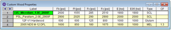
If you prefer to use a material that is not listed in the design code glulam tables, please enter the material type as a Custom Wood Species.
Note
All Glu-Lam members should be dimensioned as "Full Sawn" using the format wXdFS (or wXdMFS for metric sizes), where "w" and "d" are the actual width and depth dimensions. If the size is entered as wXd without the FS designation, then the size will be assumed to be regular dimensional lumber.
RISA includes two redesign lists for Glu-Lams: Glu-Lam_Western for Western Species and Hardwoods (HW), and Glu-Lam_SouthernPine for Southern Pine (SP/SP).
Please note that glulam design is not supported for the 91/97 NDS design code.
To use a custom
wood material that is not part of the standard NDS or CSA O86 databases, you will
need to define the custom design properties.
To access the Custom Wood Properties spreadsheet, select Custom Wood Species from the Spreadsheets menu.
Notes:
Create and apply your custom material by doing the following:
Note
For additional advice on this topic, please see the RISA Tips & Tricks webpage at risa.com/post/support. Type in Search keywords: Custom Wood Species.
The
These parameters are defined for each member.
You may assign a unique Label to all of the members. Each label
must be unique, so if you try to enter the same label more than once you
will get an error message.
The member Shape or Section Set is reported in the second column. This value is listed for reference only and may not be edited as it is dictated by the entry in the Section/Shape column on the Primary tab.
The
See the Unbraced Lengths topic.
See the Unbraced Lengths topic.
Please see below for information about the various wood adjustment factors.
See the Unbraced Lengths topic.
The NDS has a number of adjustment factors that are applied to the various allowable stresses to determine the capacity of the member. The adjustment factors are summarized in section 2.3 of the code. The following topics help to summarize how adjustment factors are obtained and used.
Note
CD is the Load Duration adjustment factor used for ASD codes. It is entered on the Load Combinations spreadsheet for each load combination for which you want wood code check results. The CD factor must be entered for each individual load combination because the CD factor is dependent on the types of loads that are applied in each load combination. Therefore, different load combinations could have different CD factors. For example, per the NDS 2024 specification, a load combination that had only dead load, would have a CD factor of “0.9”, while another combination that was comprised of dead load plus wind load would have a CD factor of “1.6”.
The CD factor will only be applied to wood code checks on wood members. See Table 2.3.2 in the NDS 2024 specification for the CD factors to be applied for typical loads. Appendix B has additional information about the Load Duration Factor.
Note
Cm is the Wet Service adjustment factor. It is applied when you check the Cm checkbox in the Materials Spreadsheet.
Ci is the Incision factor per Table 4.3.8 of NDS code. It is applied when you check the Ci checkbox in the Materials Spreadsheet.
Ct is the Temperature adjustment factor. It is calculated internally based on the wood Temperature value set on the Codes tab of Model Settings. See section 2.3.3 of the NDS 2024 for more information on this factor.
The Column Stability Factor, CP, and the Beam Stability Factor, CL,
are calculated internally. These calculated values are shown on
the Wood tab of the
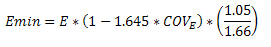
The value of Emin used for the calculation of these factors is calculated using equation D-4 from appendix D of the 2024 NDS. For some members (especially for glulams) this equation may produce a slightly more accurate value of Emin that shown in the NDS tables.
Note
CF is the Size adjustment factor. It is applied automatically when you assign a wood shape from the NDS shape database. See Tables 4A, 4B, 4D, and 4E in the NDS supplement for information on the CF factor.
Note:
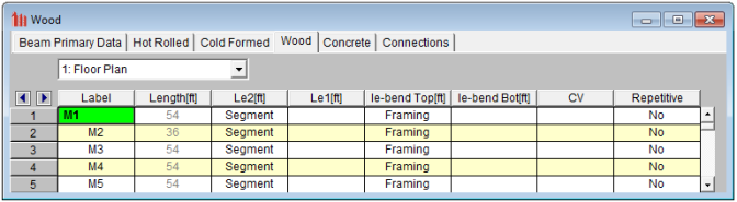
CV is the Volume adjustment factor. It is applied automatically when you assign a glulam or SCL material member. The user can override the calculated value by manually entering the factor on the Wood tab of the Beams Spreadsheet.
Note:
Cfu is the Flat Use adjustment factor. It is automatically applied to the weak axis allowable bending stress when weak axis moments are present.
For sawn lumber, in addition to the typical adjustment to weak-axis bending stress noted above, the flat use factor is also applied to the adjusted modulus of elasticity (E') and the adjusted modulus of elasticity for beam and column stability calculations (E'min) when minor-axis moments are present. Refer to NDS 2024 Table 4.3.1, Footnote 1 for more information.
Note
Cr is the Repetitive Member adjustment factor. This factor specifies if the beam is one of a group of repetitive members. This design parameter can be set on the Wood tab of the Beams Spreadsheet. If you enter 'Yes' in the Repetitive field, a factor of 1.15 will be applied to beam members that are 2" to 4" thick. See the section 4.3.9 of the NDS 2024 for information on this factor.
Note
CH is the Shear Stress adjustment factor. This design parameter can be set on the Wood tab of the Beams Spreadsheet. If left blank the program will use a default value of 1.0. See the tables in the NDS supplement for information on other CH factors.
Note
Cf is the Form adjustment factor. It is applied automatically when designing by the NDS 91/97 or 2001 Specification and a 'Round' shape is selected from the NDS shape database. See section 2.3.8 in the NDS (91/97, 2001) for information on the Cf factor.
Note
Kf is the format conversion factor for LRFD design only. The tabulated reference design values provided in the NDS Supplement contain safety adjustments appropriate for ASD. The Kf factor converts these values to nominal design values for LRFD. These factors are provided in NDS Table 4.3.1 and Appendix N.
Phi is the resistance factor for LRFD design only. These values are provided in NDS Table 4.3.1 and are dependent on the property ranging from 0.75 for shear and 0.90 for compression.
Lambda is the Time Effect adjustment factor used for LRFD codes. It is entered on the Load Combinations spreadsheet for each load combination for which you want wood code check results. The lambda factor must be entered for each individual load combination because the lambda factor is dependent on the combination of loads. Therefore, different load combinations could have different lambda factors. For example, per the NDS 2024 specification, a load combination that had only dead load, would have a CD factor of “0.6”, while another combination that was comprised of dead load plus wind load would have a CD factor of “1.0”.
The lambda factor will only be applied to wood code checks on wood members. See Table N3 in the NDS 2024 specification for the lambda factors to be applied for typical load combinations.
The CSA O86 design code has a number of adjustment factors that are applied to the various allowable stresses to determine the capacity of the member. The adjustment factors are summarized in clause 4.3 of the code. The following topics help to summarize how adjustment factors are obtained and used.
Note
KD is the Load Duration adjustment factor. It is entered on the Load Combinations spreadsheet for each load combination for which you want wood code check results. The KD factor must be entered for each individual load combination because the factor is dependent on the types of loads that are applied in each load combination. Therefore, different load combinations could have different KD factors. For example, per the CSA O86 -2009 specification, a load combination that had only dead load, would have a KD factor of 0.65, while another combination that was comprised of dead load plus wind load would have a KD factor of 1.15.
The KD factor will only be applied to wood code checks on wood members. See Table 5.3.2.2 in the CSA O86 - 2014 specification for the KD factors to be applied for typical loads.
Note
Ks is the Service Condition adjustment factor. It is applied when you check the Ks check-box in the Materials Spreadsheet. See clause 6.4.2 (sawn lumber) or clause 7.4.2 (glulams) in the CSA O86-14 for more information on this factor.
CV is the Shear Load coefficient for glulam members. It is applied automatically when you assign a material from the CSA Table 7.3 glulam material database. By default this value will always be taken as 1.0. However, the user can override this value by manually entering the factor on the Wood tab of the Beams Spreadsheet.
KH is the System adjustment factor. This factor depends on the System Factor selection applied to the member on the Wood tab of the Members spreadsheet:
Note
KZ is the Size factor. It is applied automatically when you assign a wood shape from the CSA shape database. See Table 6.4.5 in the CSA O86-14 design code for information on this factor.
KL is the Lateral Stability factor. This factor is calculated internally per the equation given in clause 7.5.6.4.4 for both glulam and full sawn members.
The final calculated values of both CB and KL are shown on
the Wood tab of the
Note:
KC is the Slenderness factor. This factor is calculated internally per the equation given in clause 6.5.6.2.4 for full sawn members and per clause 7.5.8.5 for glulam members.
Note:
The Flat Use factor is just called "Flat Use" in the member detail report. There is no explicit factor for this defined in the CSA O86-14 design code. However, there is a note for Table 6.3.1C (Material Strengths for Beams and Stringers) that includes a flat use adjustment factor. The program will determine this factor based on the asterisk table under Table 6.3.1C.
RISA will calculate the Emin value for NDS wood materials rather than read it in from the design tables. In the 2024 edition of the NDS, Emin is calculated per equation (D-4) from Appendix D.
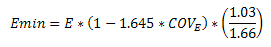
COVE (the coefficient of variation in modulus of elasticity) comes from Table F1 in Appendix F.
Note
The Design Results Spreadsheet displays the optimized design results for the beam elements and may be accessed by selecting Designs on the Results menu. The spreadsheet has six tabs: Hot Rolled, Cold Formed, Wood, Steel Products, Wood Products, and Concrete. The pull down list at the top of the spreadsheet allows you to toggle between floors.
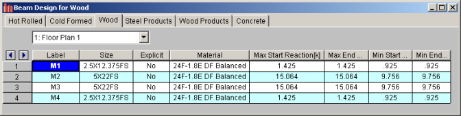
The Label column lists the beam label.
The Size column displays the optimized beam size. When no adequate member could be found from the available shapes list, this field will display the text “Not Designed”. Consider re-framing, relaxing the design or deflection requirements (see Design Optimization), or adding more shapes to the available Redesign List (see Appendix A – Redesign Lists).
The Explicit column displays “Yes” if the beam has been locked to an explicit beam size by the user. When you have chosen a specific shape to override the programs automatic redesign, that beam becomes “locked” and will not be automatically redesigned by the program.
Note
The Material column displays the material label assigned to the beam.
The Max Start & End Reactions column displays the maximum start and end reactions of the beam for ALL load combinations. If “Show Factored End reactions” in Model Settings is left unchecked, these displayed forces are not factored. If it is checked, then the displayed forces will have been multiplied by the factors in the load combinations. The sign convention assigns positive reactions to downward forces. Negative reactions, if they occur, would indicate uplift.
The Min Start & End Reactions column displays the minimum start and end reaction of the beam.
The Code Checks Spreadsheet summarizes the code check results for the beams and may be accessed by selecting Code Checks on the Results menu. The spreadsheet has five tabs: Hot Rolled, Cold Formed, Wood, Concrete, and Wood Products. The pull down list at the top of the spreadsheet allows you to toggle between floors. For more information on Hot Rolled steel design, see Hot Rolled Steel Design or Steel Design – Composite.
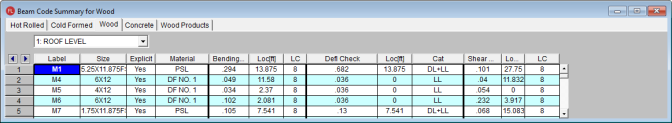
The Label column displays the beam label.
The Size column displays the beam size. When no adequate member could be found from the available shapes, this field will display the text “Not Designed”. Consider re-framing, relaxing the design or deflection requirements (see Design Optimization), or adding more shapes to the available Redesign List (see Appendix A – Redesign Lists).
The Explicit column displays “Yes” if the beam has been locked to an explicit beam size by the user. When you have chosen a specific shape to override the programs automatic redesign, that beam becomes “locked” and will not be automatically redesigned by the program.
Note
The Material column displays the material label assigned to the beam.
The Bending Check and Shear Check columns display the maximum bending check and shear check calculated by the program. This value is equal to the actual bending or shear demand (stress or force) divided by the actually beam resistance (allowable stress or ultimate capacity). You can see the details of these values in the Bending Results or Shear Results spreadsheet. This check is calculated at 100 sections along each beam for each load combination and the maximum check is reported. See Results Spreadsheets for more information.
The Deflection Check displays the maximum deflection check. This value is equal to the ratio of actual deflection to allowable deflection. You can see the details of these values in the Deflection Results spreadsheet. This check is calculated at 100 sections along each beam and the maximum check is reported. See Beam Results - Deflection for more information.
The Location columns display the location along the member where the maximum bending, shear, or deflection check occurs.
The LC column displays the controlling load combination which resulted in the maximum bending or shear check.
Deflection checks are based on Load Categories (Dead, Live or DL+LL), not Load Combinations. Therefore, the controlling load Category for deflections is reported in the Cat column.
The Shear Results Spreadsheet records the shear results for the beam elements and may be accessed by selecting Shear on the Results menu. The spreadsheet has four tabs: Hot Rolled, Cold Formed, Wood, and Concrete. The pull down list at the top of the spreadsheet allows you to toggle between floors.
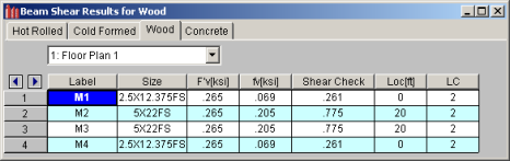
The Label column displays the beam label.
The Size column displays the beam size. When no adequate member could be found from the available shapes, this field will display the text “not designed”. When this occurs, consider re-framing, relaxing the design or deflection requirements (see Design Optimization), or adding more shapes to the available Redesign List (see Appendix A – Redesign Lists).
If you have selected an NDS wood design code, the F'v column will display the calculated allowable shear stress based on Chapter 3 of the applicable NDS code. The fv column displays the maximum actual shear stress that the member experiences.
If you have selected the CSA 086 wood design code, the Vr column will display the calculated allowable shear force based on clause 5.5.5.1 for sawn lumber, or clause 6.5.7.2.1a for glulam members (per the CSA 086-09 code). The Vf column displays the maximum actual shear force that the member experiences.
The Shear Check column displays the maximum shear check. This value is equal to the actual shear demand (stress) divided by the actual beam resistance (allowable stress). This shear check is calculated at 100 locations along each beam for each load combination. The maximum shear stress, its location, and the controlling load combination are reported. See Results Spreadsheets for more information.
The Location column displays the location along the member where the maximum shear check occurs.
The LC column displays the controlling load combination which resulted in the maximum shear check.
Note
The Bending Results Spreadsheet records the bending results for the beams and may be accessed by selecting Bending on the Results menu. The spreadsheet has four tabs: Hot Rolled, Cold Formed, Wood, and Concrete. The pull down list at the top of the spreadsheet allows you to toggle between floors.
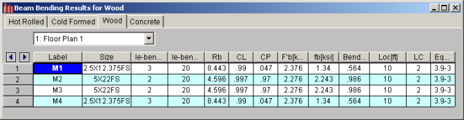
The Label column displays the beam label.
The Size column displays the beam size. When no adequate member could be found from the available shapes, this field will display the text “not designed”. When this occurs, consider re-framing, relaxing the design or deflection requirements (see Design Optimization), or adding more shapes to the available Redesign List (see Appendix A – Redesign Lists).
The Lb Top and Lb Bottom columns display the unbraced lengths associated with the controlling bending check. See Unbraced Lengths for more information on how these values are calculated.
The following adjustment factors are included in the spreadsheet:
The following adjustment factors are included in the spreadsheet:
If you have selected an NDS wood design code, th F'b column displays the calculated allowable bending stress based on Chapter 3 of the applicable NDS code. The fb column displays the maximum actual bending stress that the member experiences. The sign convention is defined so that positive bending will result in tension in the bottom fiber.
If you have selected the CSA 086 design code, the Mr column displays the calculated bending moment resistance based on clause 5.5.4.1 for sawn lumber or clause 6.5.6.5.1 for glulams. The Mf column displays the maximum actual bending force that the member experiences.
The Bending Check column displays the maximum bending check calculated by the program. This check is equal to the actual demand (bending stress/force) divided by the beam resistance (allowable stress/force). This bending check is calculated at 100 locations along each beam for each load combination and the maximum demand (stress), the location, and the controlling load combination are reported. See Results Spreadsheets for more information.
The Location column displays the location along the member where the maximum bending check occurs.
The LC column displays the controlling load combination which resulted in the maximum bending check.
The Equation column displays the code equation that controlled in the calculation of the bending check.
The Column Results Spreadsheet summarizes the code check results and records the design results for columns and may be accessed by selecting Column Results on the Results menu. The spreadsheet has four tabs: Hot Rolled, Cold Formed, Wood, and Concrete.
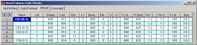
The Stack column displays the column stack label.
The Lift column displays the lift number for the physical column. Lift No. 1 is the lowermost physical column in a stack and the lifts are numbered sequentially moving up the column stack.
The Shape column displays the physical column size. When no adequate member could be found from the available shapes, this field will display the text “not designed”. Consider re-framing, relaxing the design or deflection requirements (see Design Optimization), or adding more shapes to the available Redesign List (see Appendix A – Redesign Lists).
The Code Check column displays the maximum combined axial and bending check calculated by the program. This value is equal to the actual combined axial and bending demand (stress or force) divided by the actually column resistance (allowable stress or ultimate capacity). You can see the details of this value in the subsequent Axial Resistance and Flexural Resistance columns of this spreadsheet. This check is calculated at 100 sections along each physical column for each load combination and the maximum check is reported. See Results Spreadsheets for more information.
The Shear Check column displays the maximum shear check calculated by the program. This value is equal to the actual shear demand (stress or force) divided by the actual column resistance (allowable stress or ultimate capacity). You can see details of this value in the subsequent Shear Resistance column of this spreadsheet. This check is calculated at 100 sections along each column for each load combination and the maximum check is reported. See Results Spreadsheets for more information.
The Elev columns displays the absolute elevation along the column stack where the maximum code check occurs.
The LC column displays the controlling load combination which produced the maximum code check and/or shear check.
The Dir column displays the column local axis along which the maximum shear check occurs.
If you have selected an NDS design code, the following capacities will be displayed:
If you have selected the CSA 086 design code, the following capacities will be displayed:
The Eqn column displays the code equation used in the calculation of the controlling code check.
In some instances code checks are not performed for a particular member. A message explaining why a code check is not possible will be listed instead of the code check value. You may click the cell that contains the message and look to the status bar to view the full message. Following are the messages that may be listed:
This is the general message displayed when code checks were not performed for a member. It could mean that you have not selected a Design Code in Model Settings or you have not included any load combinations for this material type in your solution. Check the Design tab of the Load Combinations spreadsheet.
Section 3.3.3.7 of the NDS code limits the slenderness ratio RB to a maximum of 50. Similarly, clause 7.5.6.4.3 of the CSA O86 limits CB to a maximum of 50. You will need to reduce the effective span length, increase the thickness of the shape, or reduce the depth of the shape.
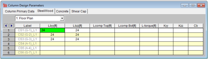
Section 3.7.1.4 of the NDS code limits the column slenderness ratio of Le1/d or Le2/b to a maximum of 50. You need to reduce your effective length by reducing the actual length between supports or changing the effective length factor “K”. You can also use a thicker shape.
Section 3.9.2 of the NDS code limits the actual axial compressive stress to be less than the term FcE1. This term is approximately the Euler buckling stress for buckling about the strong axis of the member. (Buckling is in the plane of bending)
Section 3.9.2 of the NDS code limits the actual axial compressive stress to be less than the term FcE2. This term is approximately the Euler buckling stress for buckling about the weak axis of the member. (Buckling is in the plane of bending)
Section 3.9.2 of the NDS code limits the actual strong axis bending compressive stress to be less than the term FbE. This term is approximately the lateral buckling stress.